Flying Fox gets a new engine
When we bought Flying Fox the engine looked near immaculate and, I think, had probably been well looked after. It certainly seemed to run OK, if a little noisily. It was then the same age as the boat, so I factored into the price the possibility of having to replace it within the first few years.
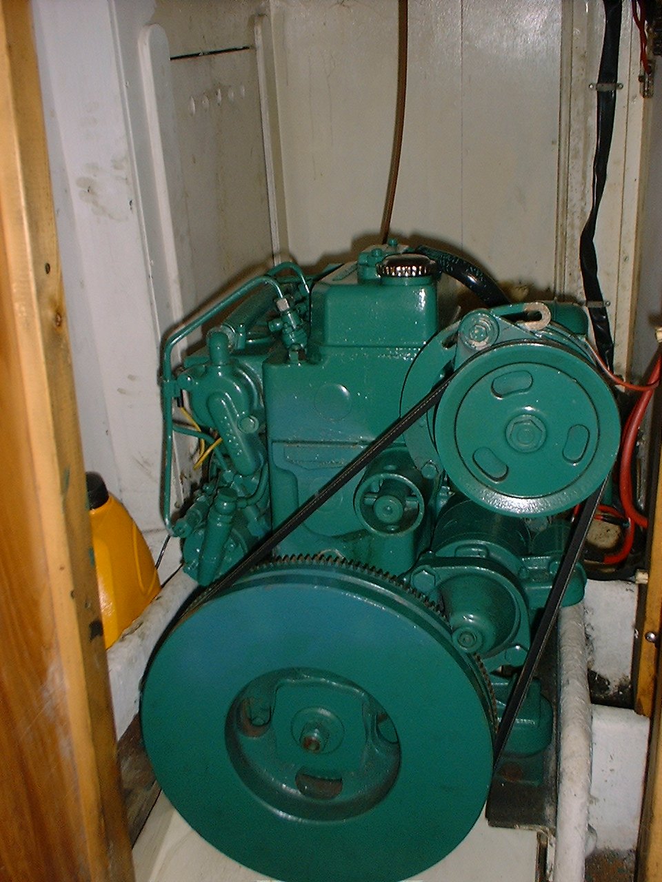
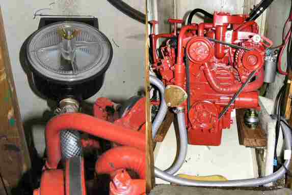
Our Volvo MD7A
During the 2004 season we suffered from a couple of engine breakdowns as explained elsewhere. I managed to fix the engine up to get us to the end of the season. I was then faced with spending probably a few hundred pounds to get the head properly sorted (but with the possibility that, next season, something else very expensive would break) or biting the bullet. After much heartache and wallet searching I decided that we had to have a reliable engine so there was little else to do but find the money and find the engine.
Calculating the power
The old Volvo, at 13HP, had seemed plenty powerful enough for what we required but I knew of other Stag owners who had re-engined with a more powerful 20 - 25HP. So out came the books to find the calculations for required horsepower.
First, calculate the maximum (theoretical) hull speed:
= 1.4 * (LWL)-2 That's the square root of Load Waterline Length
= 1.4 * (24.5)-2 Flying Fox is 24.5 ft on the LWL (roughly)
= 6.93 Knots
Then calculate the HP required to get to a sensible actual speed (I did it for 6 knots):
Speed/(LWL)-2 = 10.665 / (displacement / HP)-3 Displacement is in lbs
=> 6.0/(24.5)-2 = 10.665 / (8000 / HP)-3 That's roughly the right displacement
=> Working it out comes to 11.75 HP That's handy
I then did the same calculation for 6.5 knots which gives 14.9 HP. Wow! quite a jump.
That was for power at the prop...so, assuming 6% loss in transmission, that translates to an engine rating of 12.5 HP for 6 knots and 15.8 HP for 6.5 knots.
The Choice
At the Southampton boat show I trawled the engine manufacturers stands looking for anything in my power range. The names included Vetus, Volvo, Nanni, Beta, Yanmar and Sabb all of whom had offerings in the range 10 - 20HP. I collected all the literature and drawings that were available. I spoke, sometimes at length, to the various representatives asking every question I could think of, some questions must have sounded really dumb as I knew very little about diesel engines nor how to fit them.
The Deciding Factors
Vetus were endearingly cheap and talked to me at some length (though always with an eye out for a more expensive looking customer). Nanni were reasonably priced and very interested to get my custom. Beta were second cheapest and I got the undivided attention of their chap for a half hour or more, he was also very knowledgeable about what I was about to attempt. The others just didn't seem interested and were rather more expensive.
I knew that several Stags and loads of Vegas had already used Beta engines. I was told it was almost a direct replacement in terms of the spacing of the feet etc. I had good reports on Beta from other members of my sailing club. Their Boat Show deal was very tempting.
Back to the boat, measuring tape in hand, and all the drawings. After a little contemplation it had to be the Beta 13.5HP BZ482. Next day I phoned Beta, spoke to 'my man' and said if he'd throw in the shallow sump (a £100 extra) with the Boat show package I'd order there and then. Like a champ he said yes, so I ordered. The whole deal cost £2890 which included control panel with tacho, shallow sump, flexible coupling, feet etc. I decided to collect the engine myself both to save another £60+ and to see their factory.
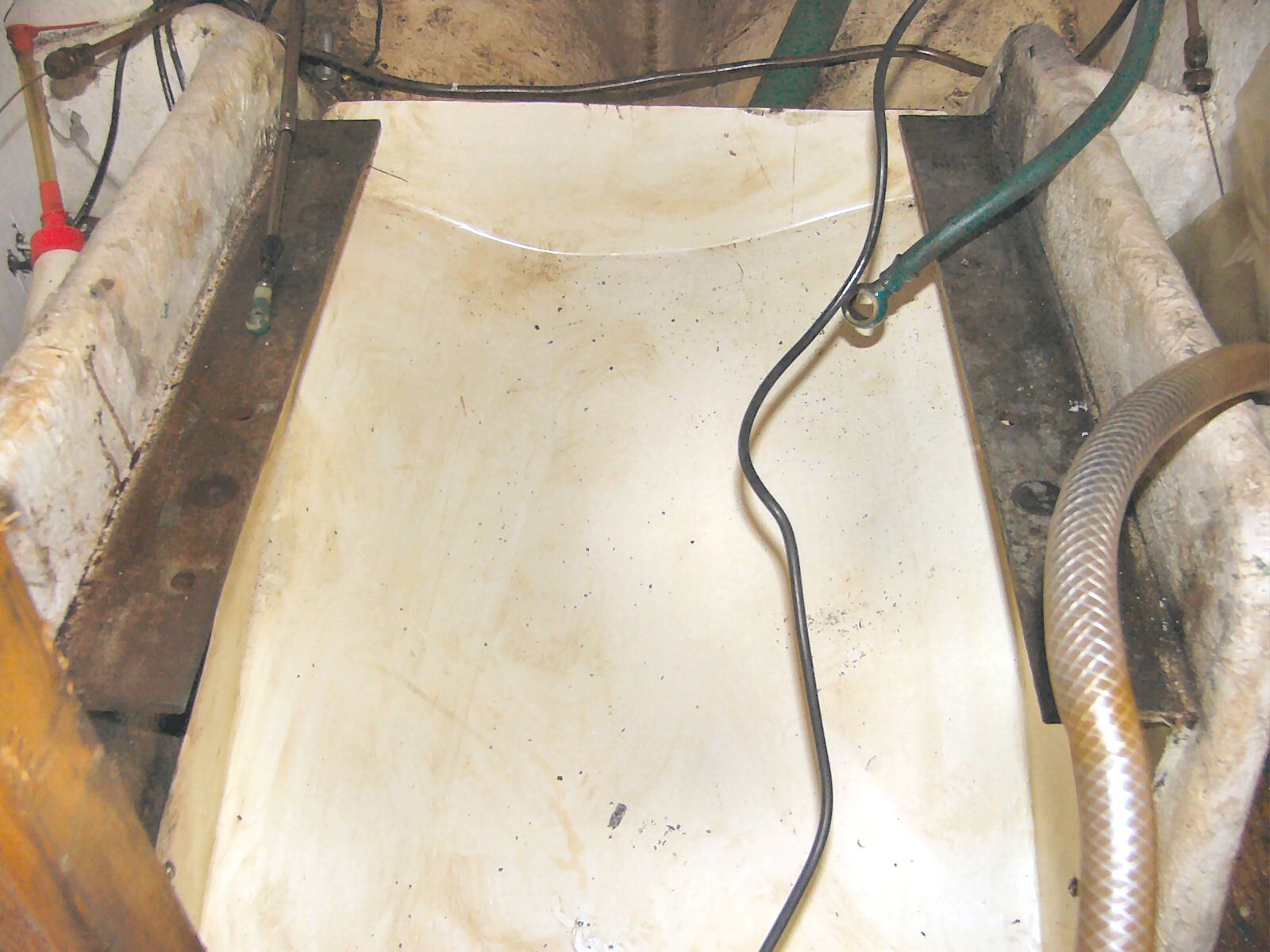
Removing the Old Volvo
Once we were ashore for the winter, I lost no time in attacking the Volvo. I disconnected all the wiring, the diesel delivery and overflow pipes, the water input, gear, throttle, cold start and stop cables and finally the exhaust pipe (hacksaw job). Because I had already done it twice that year, I also removed the head to try to reduce the weight (my 'botch up' fix to the head/waterway looked perfect). There was no way the flywheel was going to move so I moved on to disconnect the old flexible coupling from the shaft. Finally the bolts came out of the flexible feet and she was free.
Now came the interesting bit...I rigged a 4 part tackle horizontally from engine to mast support and slid a scaffold plank, on some bits of dowel, under the sump. When I stood on the end of the scaffold plank, the engine lifted a half inch off the bearers and, with the tackle, I hauled it along the plank. It needed a few wiggles to keep it straight and to get it out of the entrance to the engine bay, but finally it was on the cabin floor directly below the hatch.
A scaffold pole was supported either side of the hatch and the tackle suspended from that to the engine. Now came the time for assistants (3 of them). Haul up to hatch height, scaffold board from cockpit under the sump with 2 people standing on the other end. Slide the engine out into the cockpit, along the board. Lift and block the board a few times until the plank can be spun round 90 degrees to lay across the cockpit coamings. Slide the engine to the edge of the boat, and...No, I didn't have the bottle to just drop it over the side. Put a ladder up from ground level to the underside of the plank. Fix block and tackle to the engine from a winch base. Tip the plank so it lies down the ladder and lower away on the tackle as the engine slides neatly to the ground.
That all sounds fairly simple but the engine weighs a ton (slight hyperbole) and the whole operation took a full day to complete.
Measuring Up
How on earth to measure up a 3-dimensional jigsaw?
The first thing was to make sure the feet would sit on the existing bearers without having to replace them. I very carefully measured out a template showing the position of the feet relative to the centreline of the engine. The template also was made with the overall fore and aft dimension of the block and gearbox. When the template was placed on the existing bearers I could see that the feet were about the same width of the old ones but they were differently spaced lengthwise. Moving the template back and forth, to get the front of the engine at the correct position, gave me the position of the feet on the bearers.
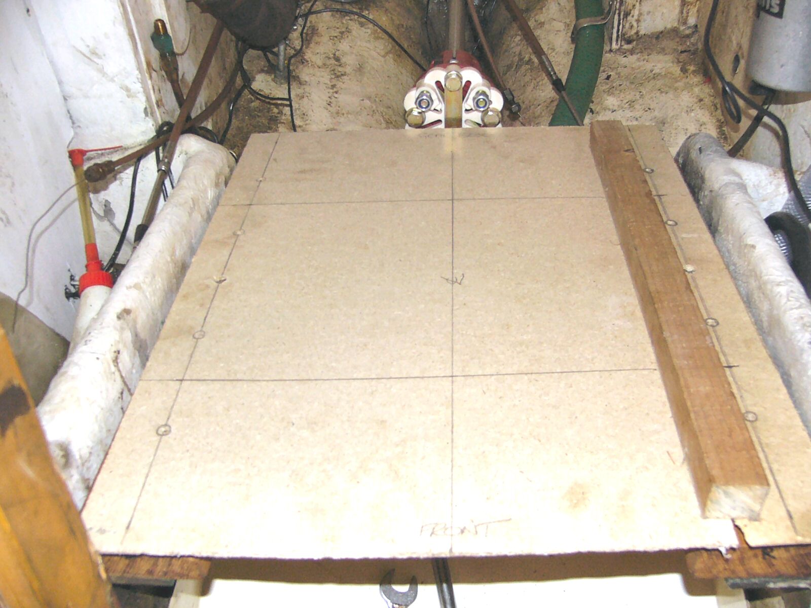
Sliding the prop shaft forward to meet the back of the template gave me the vertical height of the centre of the shaft above the bearers. This turned out to be 40mm. I also, now, could see that I needed a new, longer by 180mm, prop shaft. Going back to the drawings it turned out that the output from the gearbox was 10mm above the base of the feet at their mid-adjustment point. So, to get the gearbox output in line with the propshaft I had to raise the engine a further 30mm.
I now needed to order the new propshaft and, after much ringing around, I used a local firm (Portchester Engineering) who made one up for me within 3 days at a very reasonable £80. I also got the local joinery firm to machine up a couple of blocks of good old English Oak, 30mm thick, to act as the packing pieces to raise the engine. When the prop shaft was ready, it was slid into position and the half coupling fitted and bolted as tightly as possible. I fitted the flexible coupling at this point while there was plenty of space to wield the spanners. The two oak blocks were bolted onto the bearers after getting a couple of coats of varnish. With the blocks in position, the template was repositioned and the bolting positions marked. The holes for the bolts were drilled.
Bits and Pieces
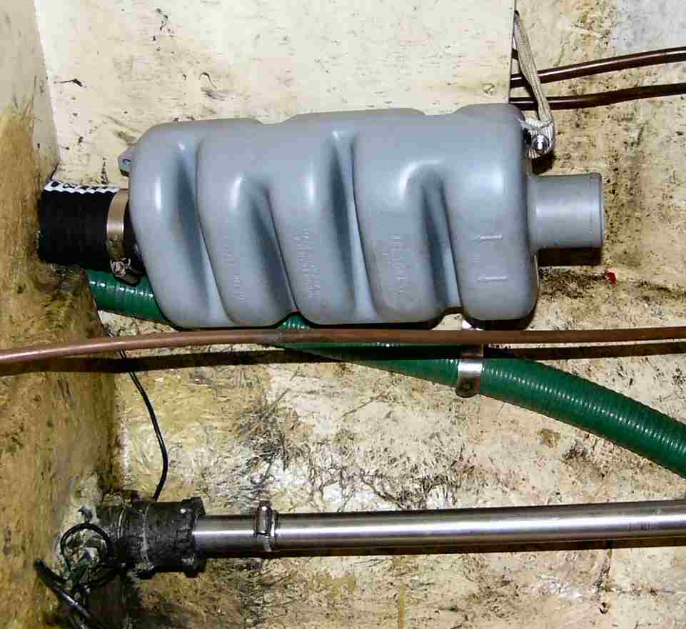
At this point I still hadn't taken possession of the engine, so, whilst the engine bay was empty I took the opportunity to replace some of the auxilliary bits and pieces. The old exhaust pipe was 45mm id whereas the new engine needed 50mm. It was also on the opposite side of the engine. Rather than replace the whole exhaust system, I retained the stern fitting and the pipe forming the swan neck. I then added an adapter to switch to 50mm pipe for a short run into the engine bay where I placed a new 50mm muffler which, I hoped, was also big enough to form a water trap. It is supported by a webbing strop
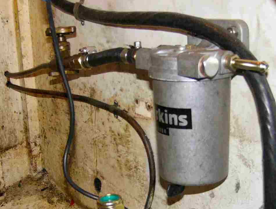
I had picked up a decent sized Perkins water separator at a boat jumble so I fitted that onto the end of the fuel line. This involved a long search for pipe fittings to fit the old fuel shut off tap which I couldnt remove because of the tank full of diesel it was holding back. The old system used taper fittings which nobody seems to make anymore.
Collecting the Engine
Collection day finally arrived and I took the day off work to drive over to the picturesque area around Stroud in Gloucestershire. The factory isn't a high tech, robot assembly plant. It's more like a family business. There are hundreds of engines stacked, waiting for marinisation or despatch. I was shown along the 'assembly line' where pieces were removed and new pieces added. The engines arrive painted a dull black and, by the time Beta have finished with them, they are very red (most of them). All the engines are tested once they are built then drained down ready for despatch. I was shown to my engine and the packing removed to reveal the beast. The fork lift picked it up and headed for the back of the estate car only to find that it was 3 inches too tall to fit. Much scratching of heads followed, I was quite prepared to lay the engine on it's side but they wouldn't hear of it. The decision was made to rebuild the pallet that it was bolted into. I had the good humoured services of three workers to remove the engine from the pallet, dismantle, cut down and rebuild the pallet 4 inches lower than it had started off. At the next attempt the engine slid neatly into the boot and, having given the guys a big enough tip to buy a few pints of beer, I headed off for home. The drive home was very careful, not fancying a diesel engine coming through the car if I got involved in an accident.
Back at the boat, getting the engine on board was the opposite of getting the old one off. The only difference being that this engine could be easily manhandled by two people. We kept the engine bolted into its pallet until it was safely in the cockpit. Then, with the help of block and tackle, out of its pallet and down onto the cabin sole.
Control Panel
While waiting for the various parts I took the opportunity to fit the new control panel. The old one had been fitted into the gap under the companionway step and, rather than add to the amount of work required, I fitted the new one in the same position. Despite the new one having a tachometer it was designed to the same size as the Volvo panel so fitted straight into the old hole with very little extra cutting required. When I've got more time I really must try to sort out the electrics which are a tangle of wires behind the panel. At least they all seem to work OK at present.
Into the Engine Bay
By this time the engine bay was ready to receive the engine and I started to pray that the drawings had been correct. I fitted the flexible feet at roughly the height I had calculated. Using the same technique of sliding the engine along a plank into the bay then tilting the plank to lower the engine onto its feet it was soon in position. Thankfully, with a bit of jigging, the bolt holes all lined up and the feet were bolted down. I used split washers and Nylock nuts to combat any vibration trying to undo the nuts.
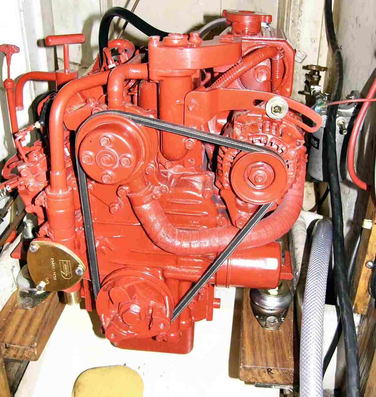
Much jigging of the thwartships position of the feet and the height of the legs eventually allowed the bolts on the shaft to slide without force into the gearbox coupling. Everything was then tightened up and the shaft slid in and out to ensure it still moved freely. The shaft was bolted to the gearbox coupling, I had to 'guess' at the torque settings as there was no way to fit a torque wrench to the bolts. More jigging of the four legs now ensued as the engine had to be lined up to give no more than 10 thou difference in the deflection of the flexible coupling around its circumference. Once all lined up and bolted tight, I was quite surprised at how rigid the engine now felt, it was much 'taughter' than the old Volvo.
Connections
Now come the multiple tasks of making all the connections for electrics, water, fuel, exhaust, control cables etc. First step was to plug the wiring loom into the engine. The excess wire was put into a big loop clipped to the wall of the engine bay. The next easiest connection was a short run of exhaust hose to join up to the muffler.
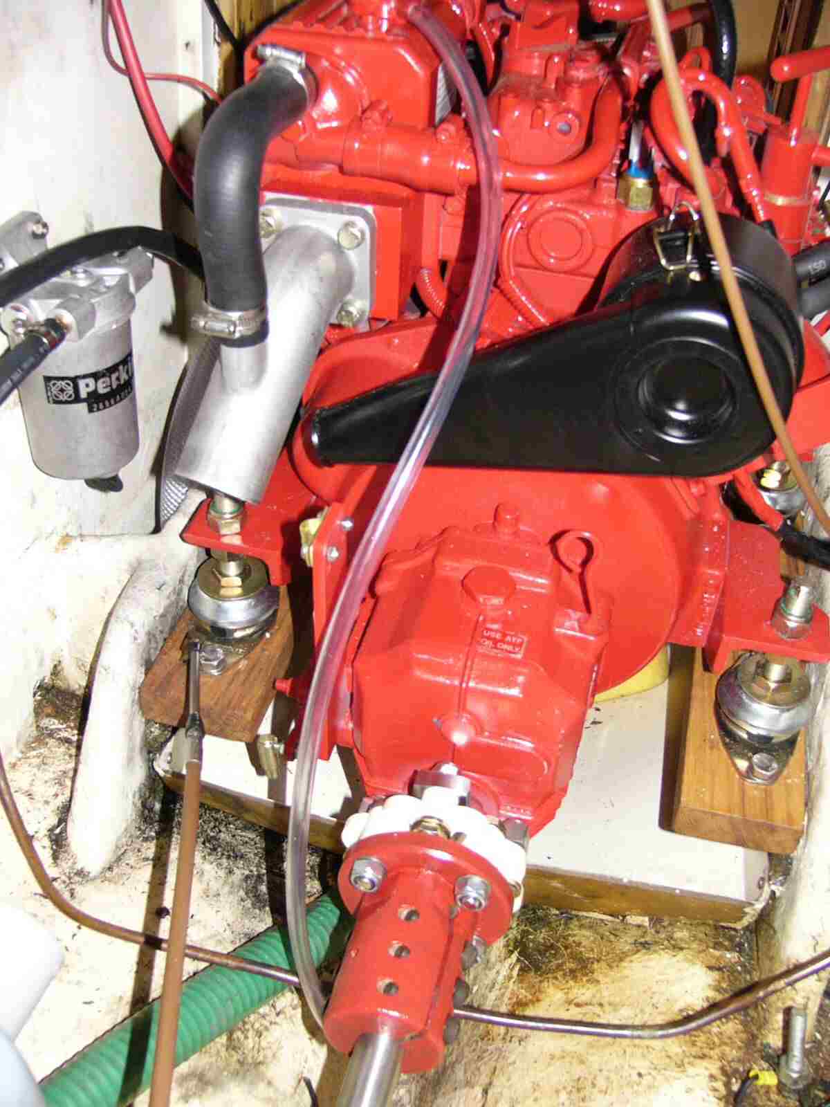
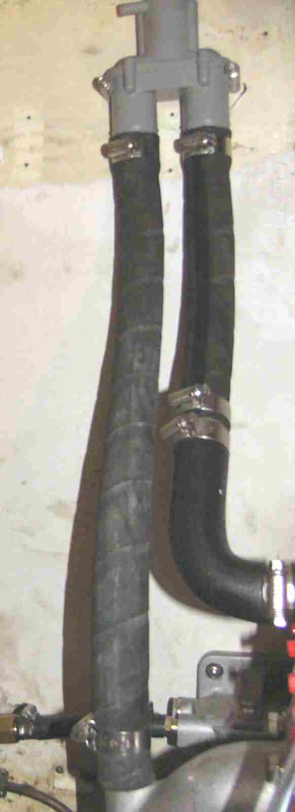
Beta insist that a syphon break should be installed between the heat exchanger and the exhaust elbow to prevent the possibility of water syphoning through the engine into the exhaust pipe then back filling into the exhaust ports. This involved turning the supplied water pipe through 180 degrees, so that it points vertically up. Joining this to a straight length of pipe up to a Vetus syphon break, positioned high in the engine bay, and another straight length to return the water to the exhaust elbow. If the syphon break without a valve is fitted then a length of pipe has to be fitted to take the overflow water through the hull above the water line.
The raw water supply to the engine is taken from a seacock with its integral strainer. I took the opportunity to add a new, bigger, raw water strainer. The only sensible place to fit this was on the opposite side of the engine bay to the inlet which meant routing the piping across the bay.
Next connections were a straightforward piece of 8mm flexible fuel pipe from the water separator, across the top of the engine, to the male fuel inlet stub. The pipe was cable tied at several points on the engine to minimise vibration wear. The copper diesel return pipe was a non-metric size fitted with an old type of taper fitting on the end. I really did not wish to have to replace this pipe so I used the old Volvo return pipe, which had the taper fitting at one end, and cut the fitting off the other to fit onto the male stub at the engine.
The gear control cable came next. This had to be re-routed so that it would enter the gearbox fitting vertically. Luckily, the existing cable was in good condition and long enough to make the loop.
The throttle cable decided to cause a problem by being set to push, whereas the engine needed it to pull. This meant removing the panelling covering the back of the gear lever and reversing the throttle cam. At least I got the chance to clean up the mechanism and add a little fresh grease to keep the action smooth.
Final connections were the power lead from battery, via switch, to solenoid and the earth lead direct from battery to starter mounting bolt. At this point I just couldn't resist turning the ignition key and was very pleasantly rewarded with a lit oil warning lamp and the beep of the warning sounder. I must admit, I did even turn the key to the 'Start' position for a second to see if the starter would turn over, it did.
Engine oil and gearbox automatic transmission fluid (ATF) were added and, finally, a 50-50 mix of water and antifreeze to the heat exchanger.
First Run
With everything finished I just had to see if the new engine would start up and run. Without a cooling water supply, I removed the water pump impeller to save it burning out. The fuel cock was opened and I started to bleed the fuel line. Immediately found a fuel leak on the outlet from the water separator, so had to remake the compression joint. All the other connections seemed OK with no leaks. 10 seconds on the heater plugs then a turn of the key and the engine fired and died. Two more attempts and this time (on Christmas Eve 2004) it kept going. Our new engine was up and running...